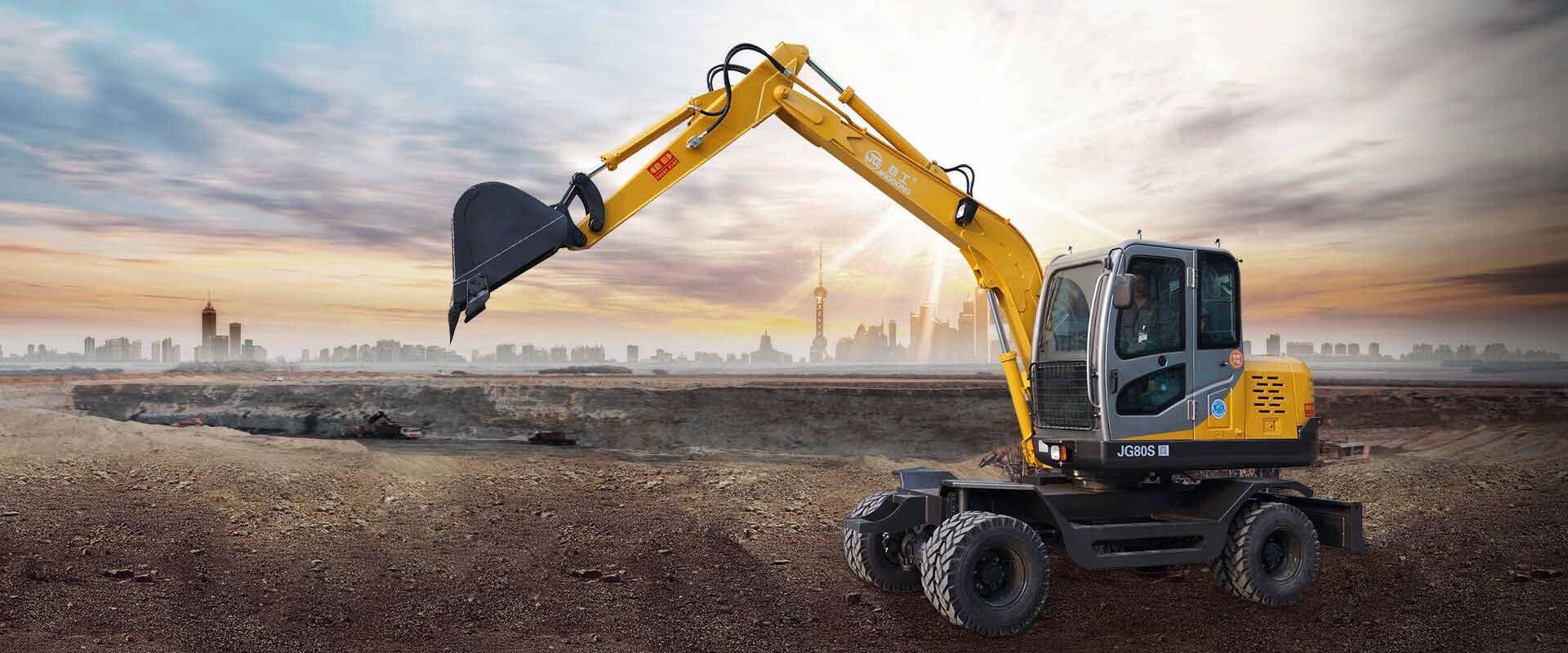
Wheel-Crawler Excavator Design:
Two Engineering Routes and Their Advantages & Limitations
A structural comparison of wheeled-based and crawler-based undercarriage architectures
A wheel-crawler excavator is not simply a wheeled excavator with tracks added, or a crawler excavator with four wheels attached. The more important question is which undercarriage architecture is used as the engineering foundation.
There are two basic design routes: (1) a wheeled-excavator-based design, which starts from a wheeled platform and integrates a crawler system; and (2) a crawler-excavator-based design, which starts from a crawler platform and integrates a wheel travel system. Both can provide wheel and crawler mobility, but their structural priorities are different. This affects stability, travel performance, ground clearance, weight distribution, maintenance and machine behavior during excavation.
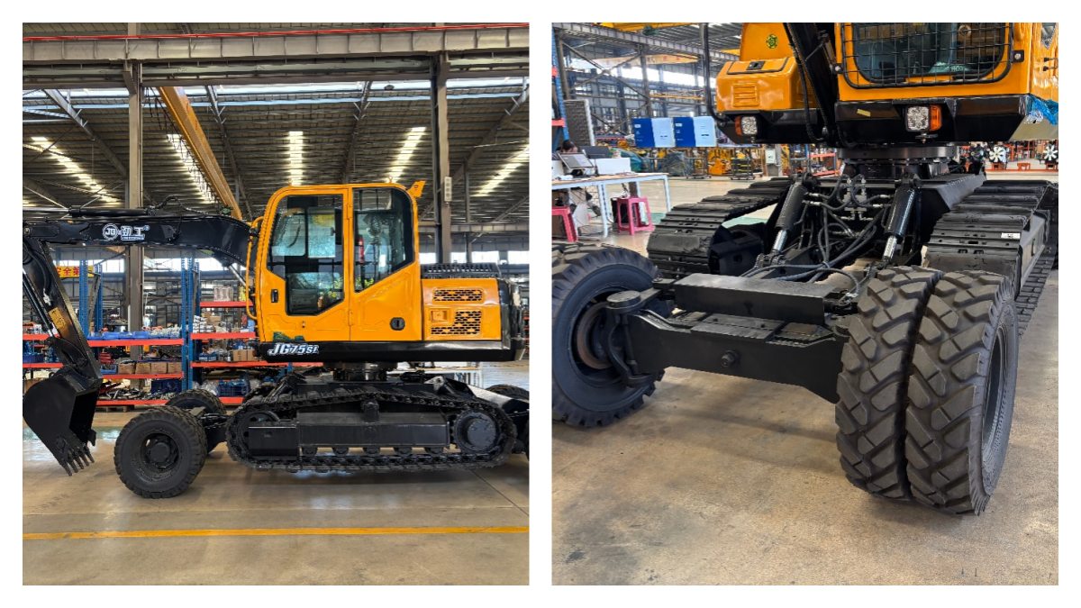
The photographs show a dual-system undercarriage in which the wheel and crawler systems are integrated into the same chassis. The crawler assemblies are positioned inside the wheel travel system, while the wheel axles and tires remain available for road travel.
In the rear view, the wheel axle and differential housing can be seen between the tires, with the crawler assemblies located above and inward of the wheels. The side view makes the relationship clearer: the crawler frame occupies the central portion of the undercarriage, the road wheels are positioned at the front and rear, and both systems must fit beneath the upper structure and swing mechanism.
The undercarriage must transmit excavation, lifting, braking and travel loads without creating excessive structural stress or unnecessary weight. The photographs alone cannot establish whether the original engineering platform was wheeled or crawler-based; that distinction must be confirmed from the original chassis design. The visible layout, however, provides a useful basis for comparing the two development routes.
This approach starts with a wheeled excavator platform originally designed around wheel axles, tires, road travel, steering, higher travel speed and road-oriented weight distribution. A crawler system is then integrated into the undercarriage.
Main advantage: mobility remains the priority
This approach naturally favors applications where the machine frequently travels between work locations. Typical applications include road maintenance, municipal construction, drainage work, agriculture, utility construction, urban excavation and short-distance relocation between work areas.
A wheeled excavator already has a chassis designed for road movement. When the crawler system is integrated correctly, the machine can retain the fundamental advantage of a wheeled platform while gaining additional ground-contact capability.
The challenge is not simply fitting tracks into the available space. The crawler system adds track frames, rollers, sprockets, drive mechanisms, hydraulic components and mass. The designer must also consider how excavation loads are transferred through the undercarriage.
A conventional wheeled excavator normally depends on its tires, axle system, blade and/or outriggers to establish working stability. A wheel-crawler machine must coordinate the wheel and crawler structures so that the added crawler system does not compromise the original chassis. Load-path design is therefore critical.
This approach starts from a crawler excavator. The original platform is built around crawler frames, track drives, rollers, low ground pressure, strong ground contact and excavation stability. A wheel system is then integrated into the chassis to provide faster travel on suitable surfaces.
Main advantage: working stability remains the priority
This design philosophy is attractive when the machine spends significant time excavating after reaching the jobsite. The crawler platform provides a large ground-contact area and distributes machine weight over the tracks, which can be beneficial on soft ground, uneven terrain, construction sites, slopes and unprepared surfaces.
The biggest challenge is integrating the wheel system without interfering with the crawler structure. The designer has to manage wheel axle position, track-frame clearance, ground clearance, wheel loading, track loading, hydraulic routing, chassis reinforcement, overall machine width and transport dimensions.
The wheel system also adds weight and structural complexity. A crawler-based design can provide strong working support, but it may sacrifice some of the simplicity and efficiency of a conventional crawler excavator.
Two machines may look similar from the outside but have different structural behavior. The critical question is: where does the excavation load ultimately go?
During digging, the bucket generates reaction forces through the arm and boom. These forces pass through the upper structure and swing bearing into the undercarriage, which must transfer them to the ground. A well-designed hybrid chassis should avoid concentrating excessive loads on individual wheel or crawler components.
Engineering area
What to examine
Swing-bearing support
Structural connection between upper and lower structures
Main chassis
Reinforcement and load distribution
Wheel axles
Vertical and lateral loading
Crawler frame
Track support and excavation loads
Wheel-track clearance
Avoiding mechanical interference
Ground clearance
Protection against obstacles and uneven terrain
Hydraulic routing
Protection from movement and external damage
Locking/support system
Secure contact during different travel modes
Comparison
Wheeled-based design
Crawler-based design
Primary priority
Road mobility
Working stability
Original platform
Wheeled chassis
Crawler chassis
Road travel
Naturally prioritized
Added as a secondary function
Soft-ground performance
Improved by crawler system
Strong crawler foundation
Excavation support
Requires careful integration
Built around crawler support
Main engineering challenge
Integrating tracks
Integrating wheels
Structural focus
Wheel chassis + crawler load path
Crawler chassis + wheel load path
Typical fit
Frequent relocation
Longer excavation cycles
Main trade-off
More complex crawler integration
Added wheel-system weight and complexity
If it frequently moves between roads, farms, construction sites or municipal projects, a wheel-oriented design may have an advantage. If it is transported to a site and works there for long periods, crawler-oriented stability may be more important.
Firm roads and prepared surfaces favor wheels. Soft, muddy or uneven working surfaces generally favor tracks because the load is distributed over a larger contact area.
A machine used mainly for travel and light excavation has different priorities from one performing continuous digging, lifting or slope work.
Inspect the chassis, axle mounting, crawler frame, structural reinforcement and the connection between the upper and lower structures—not only the tires and tracks.
Travel performance is only half of the equation. The machine must also remain stable when the upper structure swings, the boom reaches laterally and the bucket encounters resistance.
Two travel systems require more mechanical and hydraulic components than a conventional wheeled or crawler excavator. This can increase manufacturing complexity, maintenance points, machine weight, hydraulic integration requirements and the difficulty of accessing components.
The wheels, axles, crawler frames and upper structure must coexist within a limited chassis envelope. The designer must balance wheel size, track width, ground clearance, stability, overall width and structural strength. Larger wheels may improve road clearance but consume space needed by the crawler system; wider tracks may improve ground contact but increase transport width.
The value of this architecture is not that it completely replaces conventional wheeled or crawler excavators. Its value is that it attempts to cover the gap between the two. A conventional wheeled excavator is useful when mobility is important but may be limited on poor ground. A conventional crawler excavator provides strong working support but normally requires transportation for long road travel.
A wheel-crawler excavator attempts to combine these characteristics in one machine. The engineering challenge is to achieve this combination without allowing additional system weight and complexity to outweigh the operational benefit.
Is a wheel-crawler excavator better than a normal wheeled excavator?
Not always. Its advantage appears when the machine must work across a wider range of ground conditions.
Is it as stable as a conventional crawler excavator?
That depends on the undercarriage architecture, weight distribution, track contact area and working configuration. The presence of tracks alone does not guarantee crawler-level stability in every operating condition.
Which design is easier to manufacture?
Neither is universally easier. A wheeled-based design has to integrate the crawler system into a wheel-oriented chassis, while a crawler-based design has to integrate wheels without compromising the crawler structure.
What should buyers inspect first?
Inspect the complete undercarriage, especially the chassis load path, wheel axle support, crawler frame, ground clearance, hydraulic integration and the relationship between the two travel systems.
The most important difference between the two wheel-crawler excavator architectures is not whether the machine has wheels or tracks. It is which system forms the original structural foundation.
A wheeled-excavator-based design generally places greater emphasis on road mobility and frequent relocation. A crawler-excavator-based design generally places greater emphasis on ground contact and excavation stability.
The photographs illustrate the engineering challenge: wheels, axles, crawler frames and the upper structure must share the same limited undercarriage space while maintaining an effective structural load path. For buyers, the best question is not simply, “Does it have both wheels and tracks?” but “Which travel system is the machine fundamentally designed around, and does that architecture match my working cycle?”
No. 88 Pancuo, Jiaonan Village, HeShi Town, Luojiang District, Quanzhou, Fujian, China
هاتف : +8618805957336
WhatsApp : +8618805957336
البريد الإلكتروني : winny@fjjgjx.com
 شبكة ipv6 المدعومة
مسح ل wechat :

 هاتف : +8618805957336
 البريد الإلكتروني : winny@fjjgjx.com


 خريطة الموقع